

Fittings · TS-HB
Horizontal Bends 90° / 45°
Formed bends with 100 mm straight ends, for changing direction in the horizontal plane without cutting tray on site.
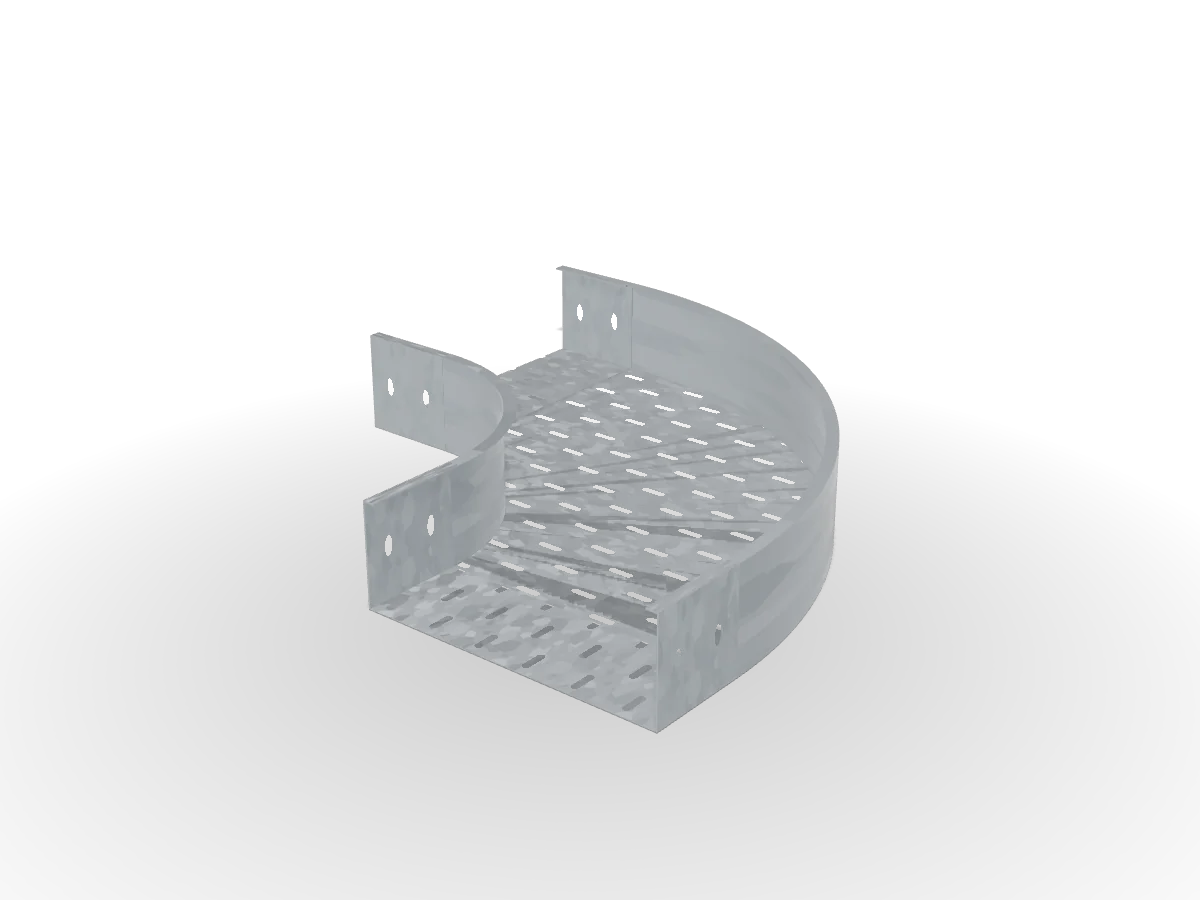 Drag to orbit · scroll to zoom
Real-time 3D · illustrative
Overview
Horizontal bends turn a run around columns, corners and shafts. The inside radius keeps cables within their minimum bending radius, and the straight ends carry the same splice-hole pattern as the trays, so the bend joins with the standard splice set. An adjustable bend covers non-standard angles.
Key features
- 90° and 45° angles
- Factory-punched splice holes at both ends
- Adjustable bend available for non-standard angles
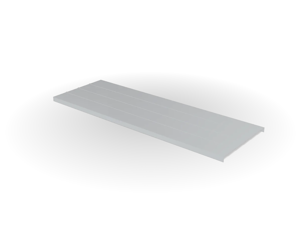
- Matching bend cover in every width
Applications
Where it is used
- Direction changes around columns and corners
- Entries into electrical rooms and shafts
Specifications
Technical data TS-HB
| Product family | TS-HB — Horizontal Bends 90° / 45° |
|---|---|
| Widths W | 50, 100, 150, 200, 300, 400, 500, 600 mm |
| Side heights H | 50, 100 mm |
| Thickness t | 1.2, 1.5, 2.0 mm |
| Length | Inside radius 300 mm; straight ends 100 mm |
| Material | Same steel grade and thickness as the matching tray |
| Perforation | Same slot pattern as the matching tray |
| Code format | TS-HB[90|45]-[W]-[H]-[finish] |
| Code example | TS-HB90-300-100-HDG |
Standards
References
- IEC 61537 (test reference)
Load data
Safe working loads and support spans will be published after type testing to IEC 61537. Until then, support spacing follows the project specification; our engineers can advise on typical spans for your cable load.
Finishes
Available finishes
System
Compatible accessories


Installation
Installation notes
- Set out and fix supportsTrapeze hangers or cantilever arms on the route line; add a support within 600 mm of each fitting.
- Lay straight sectionsKeep splice joints near supports, away from mid-span.
- Join with splice platesOne plate each side, M6 round-head bolts with heads inside the tray; tighten flange nuts.
- Lay cables and fit coversTie cables to the base slots; clip covers every metre where specified.
- Earth bondingBond the run to earth where the project specification requires it.
We prepare the technical submittal for TS-HB: datasheet, dimensioned drawings, material certificates and samples, ready for consultant review.
Request technical submittal