

Cable Trays · TS-ST
Solid-Bottom Tray / Cable Trunking
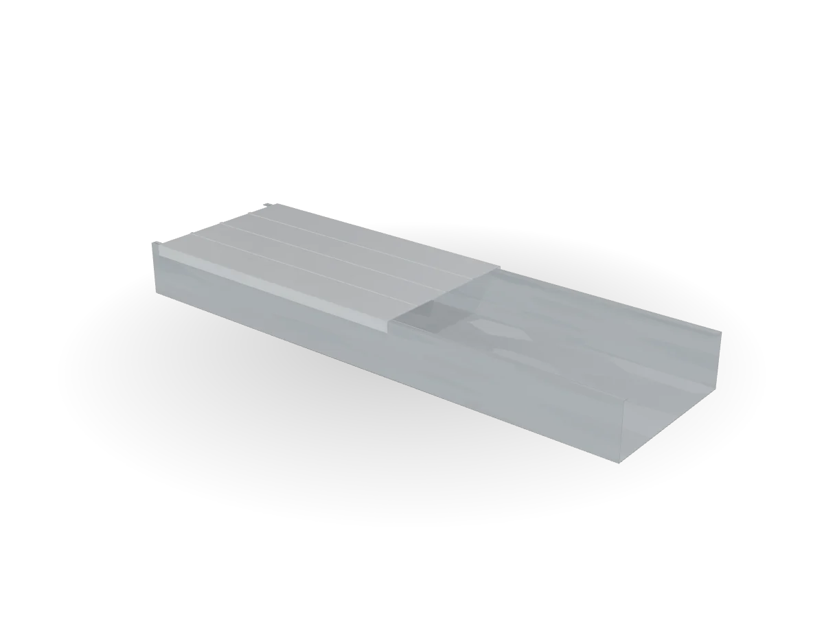
A closed base with a matching cover: full mechanical protection and clean separation of fire-alarm, data and instrumentation circuits.
 Drag to orbit · scroll to zoom
Real-time 3D · illustrative
Overview
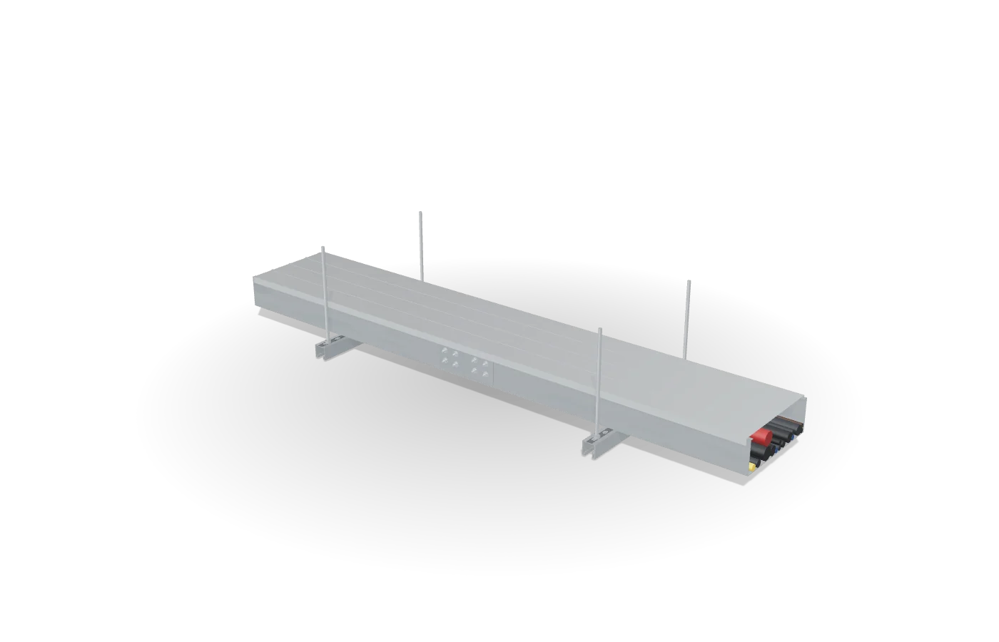
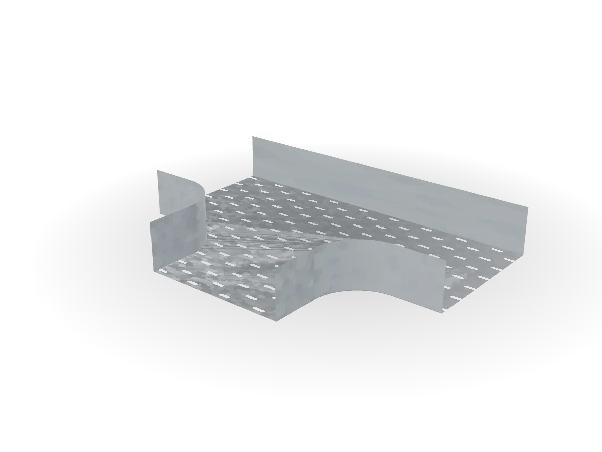
Solid-bottom tray — called cable trunking on most Egyptian sites — encloses cables completely once the cover is fitted. Consultants specify it for fire-alarm, low-current and instrumentation circuits, for exposed runs where debris can fall onto cables, and wherever two systems must run side by side without mixing.
The trunking shares the widths, heights and fittings geometry of the perforated range, so a project can switch between the two along a route. A full-length divider can be added to carry power and data in one body, and drain holes can be punched for outdoor runs.
Key features
- Full enclosure with flanged, clip-on cover
- Optional full-length divider for power / data separation
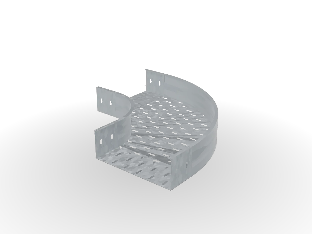
- Same fittings geometry as the perforated range
- Smooth inner surface for long cable pulls
- Drain holes on request for outdoor use
Applications
Where it is used
- Fire-alarm and life-safety circuits
- Data, CCTV and low-current systems
- Exposed runs in car parks and loading areas
- Hospital corridors and clean areas
Dimensioned section
Drawing updates with the size you pick
The section is generated from the same product data as the datasheet, so the drawing, code and table always match.
- Developed blank524 mm
- Return flange12 mm
- Standard length3000 mm
Drawings are for selection. Approved shop drawings are issued with the technical submittal.
Specifications
Technical data TS-ST
| Product family | TS-ST — Solid-Bottom Tray / Cable Trunking |
|---|---|
| Widths W | 50, 100, 150, 200, 300, 400, 500, 600 mm |
| Side heights H | 50, 100 mm |
| Thickness t | 1.0, 1.2, 1.5, 2.0 mm |
| Length | 3000 mm |
| Material | DC01 cold-rolled steel or DX51D+Z275 pre-galvanised |
| Perforation | None (drain holes on request for outdoor runs) |
| Code format | TS-ST-[W]-[H]-[t×10]-[finish] |
| Code example | TS-ST-200-50-12-PG |
Standards
References
- IEC 61537 (test reference)
- BS EN ISO 1461
- EN 10346 / EN 10130
Load data
Safe working loads and support spans will be published after type testing to IEC 61537. Until then, support spacing follows the project specification; our engineers can advise on typical spans for your cable load.
Sizes & mass
Launch range — steel mass kg/m at H = 100 mm
| W (mm) | t 1.0 | t 1.2 | t 1.5 | t 2.0 | Area W×H (mm²) |
|---|---|---|---|---|---|
| 50 | 1.89 | 2.27 | 2.84 | 3.79 | 5,000 |
| 100 | 2.24 | 2.69 | 3.36 | 4.48 | 10,000 |
| 150 | — | 3.10 | 3.88 | 5.17 | 15,000 |
| 200 | — | 3.51 | 4.39 | 5.86 | 20,000 |
| 300 | — | 4.34 | 5.43 | 7.24 | 30,000 |
| 400 | — | — | 6.47 | 8.62 | 40,000 |
| 500 | — | — | — | 10.00 | 50,000 |
| 600 | — | — | — | 11.38 | 60,000 |
— not in the launch range for that width. Minimum thickness: 1.0 mm to W100, 1.2 mm to W300, 1.5 mm at W400, 2.0 mm from W500. Other thicknesses on request.
Finishes
Available finishes


FAQ
Questions engineers ask us
Can I mix trunking and perforated tray on one route?
Yes. Widths, heights and splice holes are identical, so the same splice plates join both.
Do I need a cover on every length?
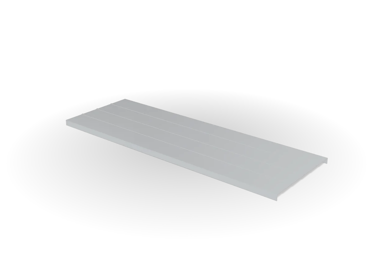
Trunking is designed to be covered. The cover is ordered separately as TS-CV in the same width.
Installation
Installation notes
- Set out and fix supportsTrapeze hangers or cantilever arms on the route line; add a support within 600 mm of each fitting.
- Lay straight sectionsKeep splice joints near supports, away from mid-span.
- Join with splice platesOne plate each side, M6 round-head bolts with heads inside the tray; tighten flange nuts.
- Lay cables and fit coversTie cables to the base slots; clip covers every metre where specified.
- Earth bondingBond the run to earth where the project specification requires it.
We prepare the technical submittal for TS-ST: datasheet, dimensioned drawings, material certificates and samples, ready for consultant review.
Request technical submittal